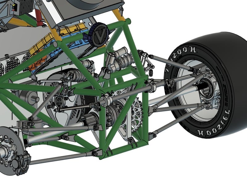
Blade Anti-Roll Bar Design
For the 2024-2025 FSAE season, I was tasked with designing a blade-style rear anti-roll bar that allowed for an appropriate change in lateral load transfer distribution (LLTD) through its adjustment range. LLTD measures the proportion of lateral weight transfer that occurs over the front axle, and is an important metric for characterizing vehicle handling (namely oversteer/understeer and agility of turn-in).
Ride and Roll Analysis
The first step in the process was to create a script to easily solve for component parameters given desired vehicle ride and roll characteristics. The script takes easily obtainable vehicle parameters as inputs, notably weight distribution and F+R CG height, F+R track width, ARB motion ratios (fixed by bell crank geometry and packaging constraints), and tire radius/spring rate.
The desired outputs were ARB system torsional stiffness and compatible spring combinations/motion ratios to achieve desired wheel rate
Two parameters were fixed to generate a set of compatible values: roll gradient (defined as the rate of body roll per unit lateral acceleration), and front ride frequency (undamped frequency of the vehicle body in ride).
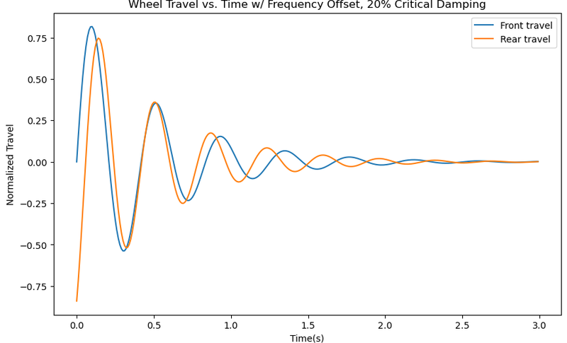
To establish a rear ride frequency that minimized pitch sensitivity of the vehicle, we find the frequency at which the rear's oscillation will "catch up" to the front at 40mph when subject to an impulse, yielding the following:
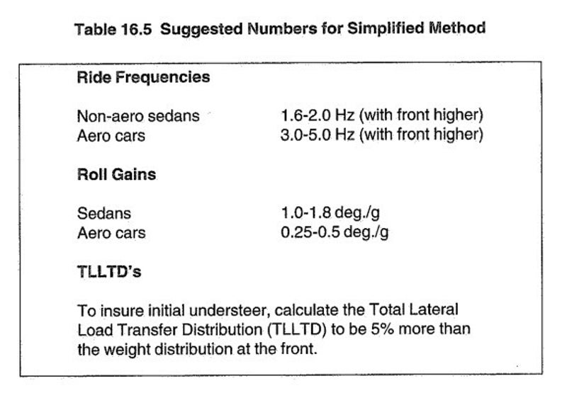
Table of suggested ride frequencies from Race Car Vehicle Dynamics (Milliken)
Once preliminary wheel rates were selected, we can find the percent of the total roll moment provided by the springs at the desired wheel rates. Using this method to ballpark the torsional stiffness of the anti-roll bar inevitably introduced some error into the roll gradient, so parameters were then tuned by stiffening the wheel rates proportionally to one another until the rear had reached the boundary natural frequency (set at 2.75Hz), at which point the desired ARB torsional stiffness was determined.
Torsion Bar and Blade Design
4130 steel was chosen for the torsion bar based on its ease of weldability, availability, and price. Titanium 6AI-4V was chosen for the blades due to its high ductility and common use in this application, although challenging to machine and costly.
Excel was used to easily iterate through parameters for the torsion bar polar moment of inertia and target blade stiffness in the softest and stiffest positions. Since the blades' stiffness is characterized by linear deflection and the torsion bar by angular deflection, the angular deflection of the torsion bar was converted to a linear deflection seen at the tip of the blade.
Maximum wheel loads came from my suspension wheel loading script. Learn more about that project here.
Initially, the blade was assumed rectangular to make hand calculations easier. The actual stiffness was determined using FEA in Fusion360 for a tapered blade geometry.
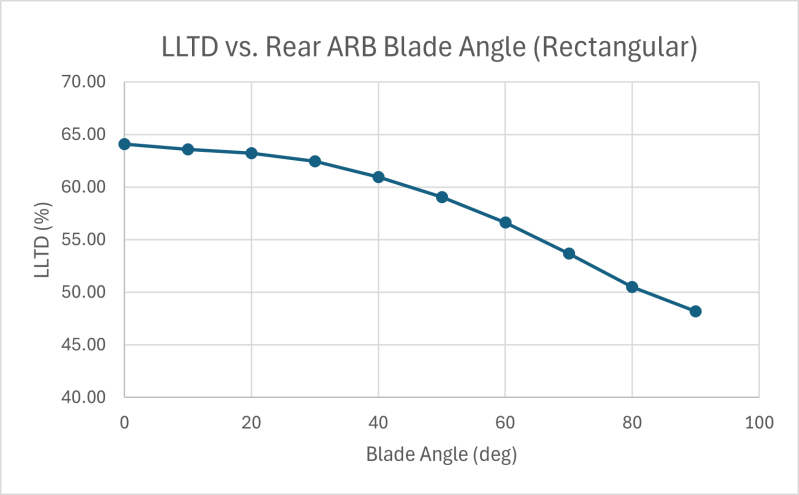
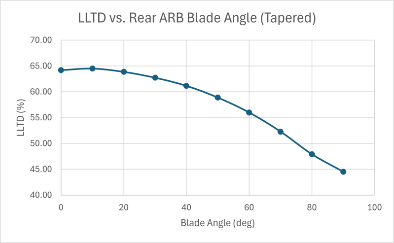
A key design tradeoff was observed during design: the more system stiffness provided by the blades, the greater the resolution but the less the adjustment range, and vice versa. After some iteration, taking into account LLTD adjustment range/resolution and system weight, the average adjustment LLTD resolution was 2.2%, which was deemed acceptable for this application due to packaging limitations.
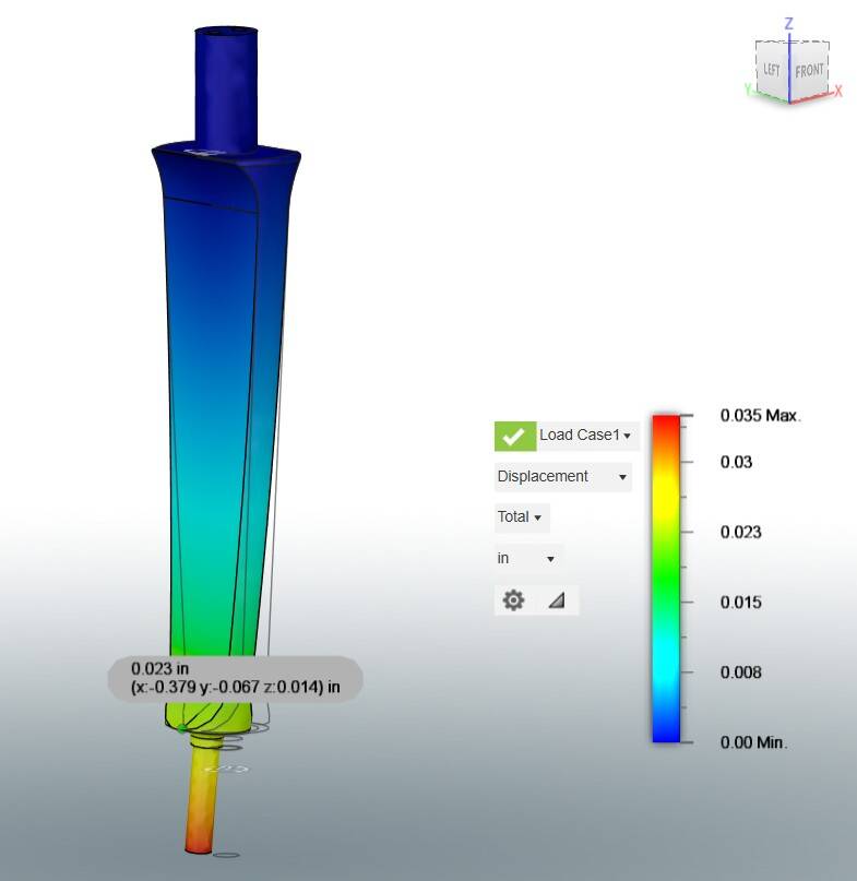
Blade FEA (SF = 3.41)
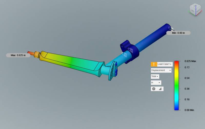
Half-ARB FEA (SF = 1.94)
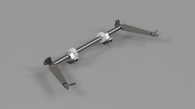
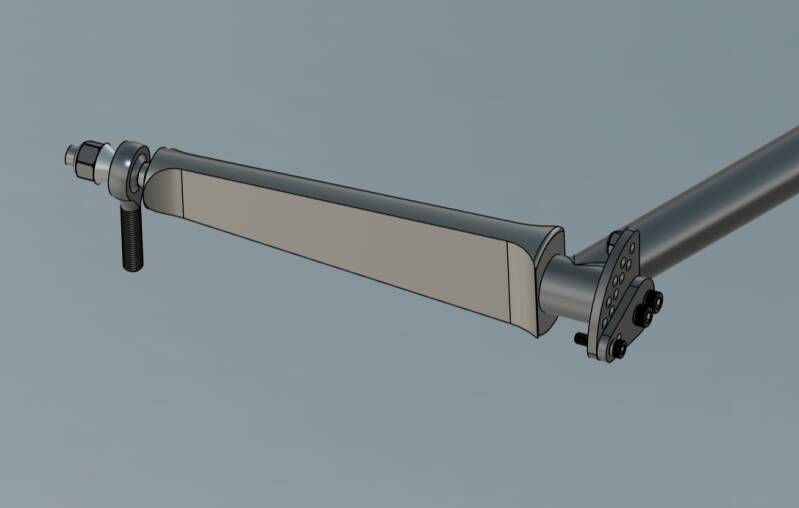
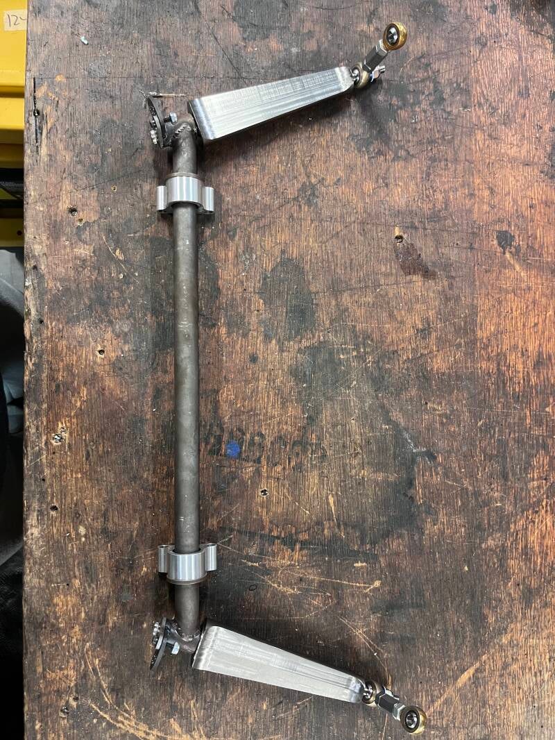
For adjustment, I designed an index plate mechanism that allowed for 10 discrete adjustment points between 0 and 90 degrees, using a tab welded to the torsion bar section with a series of offset holes to allow for more adjustment fidelity while maintaining proper tear-out. The indexing lobe is attached to the blade via two threaded holes with safety wire bolts in the top. The blade housing is a section of coped tube that is welded directly on to the torsion bar.

ARB on softest setting.
ARB on hardest setting.
To mount the ARB, two Al 6061-T6 pillow blocks (pictured below) were designed with press fit oil-impregnated iron-copper flanged sleeve bushings to house the torsion bar section. The pillow blocks are attached to the frame via 4 welded steel tabs. Nylon shaft collars were used for positive retention.

Overall parameters are summarized below.
Anti-Roll Bar System Parameters
| System Weight (lb) | 2.26 |
| LLTD Adj. Range (%) | -10.51 +9.2 |
| Minimum LLTD Adj. Resolution (%) | 4.39 |
| Average LLTD Adj. Resolution (%) | 2.19 |
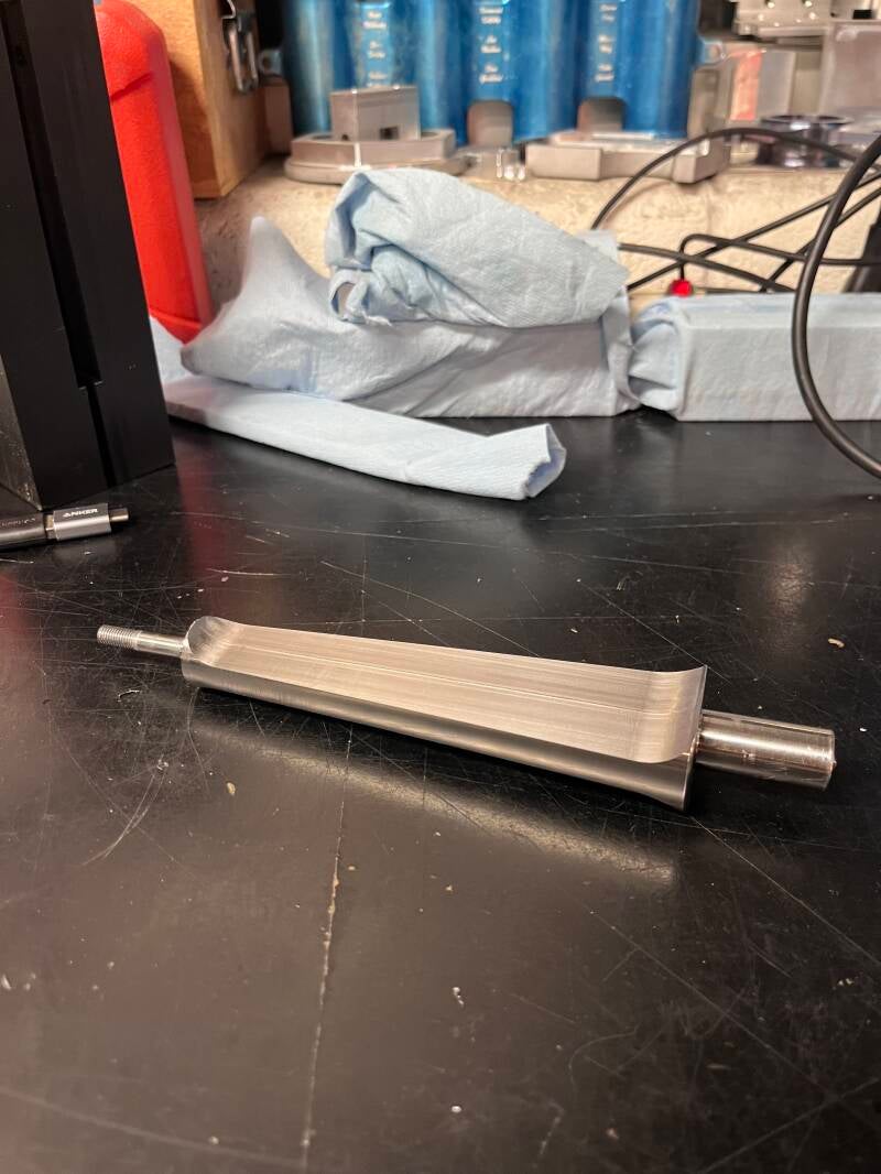
Blades were machined by my extremely talented teammate Tim Genz (https://www.linkedin.com/in/tim-genz-026606272/)